異なる継続時間の短時間停電時のコンポーネントの挙動をシミュレートしています。
このような遮断は、接点や回線のエラー、リレーのバウンドなどのイベントによって発生する可能性があります。
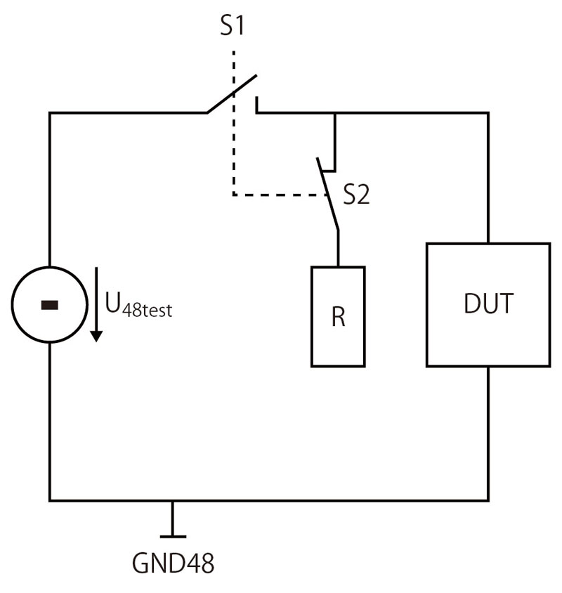
| Test setup | The principle circuit according to Fig. 15. The wiring system configuration must be coordinated with the customer’s specialist department. | |
| Ri | ≤ 60 mΩ incl. switch S1 | |
| R | 100 mΩ Total resistance incl. cable routing and switch S2 | |
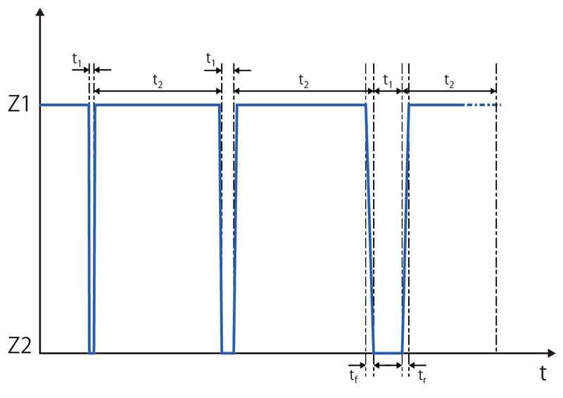
| Z1 | S1 closed and S2 open | |
| Z2 | S1 open and S2 closed | |
| U48test | U48n | |
| t1 | The supply voltage is interrupted by U48test in varying time intervals. The following sequence must be observed. | |
| 100 μs to 1 ms | 100 μs steps | |
| 1 ms to 10 ms | 1 ms steps | |
| 10 ms to 100 ms | 10 ms steps | |
| 100 ms to 2 s | 100 ms steps | |
| t1 | < 10 s The test voltage U48test must be maintained at least until the DUT has a 100% operating capability again (all systems have started up again without errors). |
|
| tf | ≤ 10 μs | |
| tr | ≤ 10 μs | |
| Number of cycles | 1 | |
| Number of DUTs | 6 | |
DUTの代替品として1kΩ(±5%)および10Ω(±5%)を使用した基準測定を各1回実施し、文書化する必要がある。